- Getting Started with the Arduino Pro Mini
- Use your Arduino Pro Mini on the Arduino Web IDE
- Use your Arduino Pro Mini on the Arduino Desktop IDE
- Open your first sketch
- Select your board type and port
- Upload and Run your first Sketch
- Learn more on the Desktop IDE
- Tutorials
- Power
- Connectors
- Как запрограммировать Arduino Pro Mini с помощью программатора
- 1 Программатор для Arduino
- 2 Установка драйвера для программатора
- 3 Схема подключенияArduino к программатору
- 3 Настройка Arduino IDEдля работы с программатором
- 4 Загрузка скетча в Arduinoс помощью программатора USBasp
- Программирование arduino pro mini программирование
Getting Started with the Arduino Pro Mini
The Arduino Pro Mini is intended for advanced users who require flexibility, low-cost, and small size. It comes with the minimum of components (no on-board USB or pin headers) to keep the cost down. It’s a good choice for a board you want to leave embedded in a project. Please note that there are two versions of the board: one that operates at 5V (like most Arduino boards), and one that operates at 3.3V. Be sure to provide the correct power and use components whose operating voltage matches that of the board.
The Arduino Pro Mini is programmed using the Arduino Software (IDE), our Integrated Development Environment common to all our boards and running both online and offline. For more information on how to get started with the Arduino Software visit the Getting Started page.
Use your Arduino Pro Mini on the Arduino Web IDE
All Arduino boards, including this one, work out-of-the-box on the Arduino Web Editor, you only need to install Arduino Create Agent to get started.
The Arduino Web Editor is hosted online, therefore it will always be up-to-date with the latest features and support for all boards. Follow this simple guide to start coding on the browser and upload your sketches onto your board.
Use your Arduino Pro Mini on the Arduino Desktop IDE
If you want to program your Arduino Pro Mini while offline you need to install the Arduino Desktop IDE
The board comes without built-in USB circuitry, so an off-board USB-to-TTL serial converter must be used to upload sketches. For the 3.3V Arduino Pro boards, this can be a FTDI TTL-232R-3V3 USB — TTL Level Serial Converter Cable or the SparkFunFTDI Basic Breakout Board (3.3V). For the 5V Arduino Pro boards, use a TTL-232R USB — TTL Level Serial Converter or the SparkFunFTDI Basic Breakout Board (5V). (You can probably also get away with using a 5V USB-to-serial converter with a 3.3V board and vice-versa, but it’s not recommended.)
If using the FTDI cable on Windows, you’ll need to make one configuration change to enable the auto-reset. With the board connected, open the Device Manager (in Control Panels > System > Hardware), and find the USB Serial Port under Ports. Right-click and select properties, then go to Port Settings > Advanced and check Set RTS on Close under Miscellaneous Options.
Open your first sketch
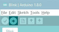
Open the LED blink example sketch: File > Examples >01.Basics > Blink.
Select your board type and port
For the 3.3V versions of the Arduino Pro Mini, select Arduino Pro or Pro Mini (3.3V, 8 MHz) w/ ATmega328P or Arduino Pro or Pro Mini (3.3V, 8 MHz) w/ ATmega168 from the Tools > Board menu (depending on the microcontroller on your board). For the 5V versions of the Arduino Pro Mini, select Arduino Duemilanove or Nano w/ ATmega328P or Arduino Diecimila, Duemilanove, or Nano w/ ATmega168.
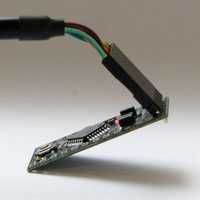
The Arduino Pro Mini connected to (and powered by) an FTDI TTL-232R-3V3 USB — TTL Level Serial Converter Cable. The green and black wires align with the labels «GRN» and «BLK» written next to the holes.
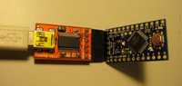
The Arduino Pro Mini connected to (and powered by) a SparkFun FTDI Basic Breakout Board and USB Mini-B cable. Note that on earlier Pro Mini boards the orientation of the 6-pin header may be reversed; check that the words GRN and BLK align on the Pro Mini and FTDI Basic Breakout.
Upload and Run your first Sketch
To upload the sketch to the Arduino Pro Mini, you need to press the upload button in the Arduino environment.
Click the Upload button in the upper left to load and run the sketch on your board:
Wait a few seconds — you should see the RX and TX LEDs on the board flashing. If the upload is successful, the message «Done uploading.» will appear in the status bar.
Learn more on the Desktop IDE
See this tutorial for a generic guide on the Arduino IDE with a bit more info on the Preferences, the Board Manager, and the Library Manager.
Tutorials
Now that you have set up and programmed your Arduino Pro Mini board, you may find inspiration in our Project Hub tutorial platform.
Power
The board can be powered through USB via the six-pin programming header or from a regulated 5V or 3.3V (depending on the model) supply applied to the VCC pin or an unregulated supply on the RAW pin.
Connectors
Any standard 0.1″ spaced header can be soldered to the holes on the Arduino Pro Mini. To use every pin requires two 12-pin headers, plus a six-pin header for programming if desired. Bare wire can also be soldered directly to the holes.
The text of the Arduino getting started guide is licensed under a Creative Commons Attribution-ShareAlike 3.0 License. Code samples in the guide are released into the public domain.
Как запрограммировать Arduino Pro Mini с помощью программатора

В жизни начинающего ардуинщика рано или поздно наступает момент, когда хочется сэкономить на размере своего изделия, не жертвуя при этом функциональностью. И тогда Arduino Pro Mini – отличное для этого решение! За счёт того, что у этой платы отсутствует встроенный USB-разъём, она в полтора раза меньше Arduino Nano. Но для того, чтобы её запрограммировать, придётся приобрести дополнительный – внешний – USB-программатор. О том, как «залить» написанную программу в память микроконтроллера и заставить Arduino Pro Mini работать, и пойдёт речь в этой статье.
Инструкция по программированию Arduino Pro Mini программатором
- Arduino Pro Mini;
- USBasp-программатор;
- соединительные провода (рекомендую вот такой набор проводов);
- макетная плата;
- компьютер c Arduino IDE.
1 Программатор для Arduino
Сначала пара слов о самом программаторе. Купить такой можно за 2 доллара в любом китайском интернет-магазине, например, в этом.

- Разъём типа USB-A используется, понятно, для подключения программатора к компьютеру.
- ISP-соединитель нужен для подключения к программируемой плате.
- Джампер JP1 контролирует напряжение на выводе VCC ISP-коннектора. Оно может быть 3,3 В или 5 В. Если целевое программируемое устройство имеет собственный источник питания, нужно убрать перемычку.
- Джампер JP2 используется для перепрошивки самого программатора; в данной статье этот вопрос не рассматривается.
- Перемычка JP3 нужна, если тактовая частота целевого устройства ниже 1,5 МГц.
- Светодиоды показывают: G – питание подаётся на программатор, R – программатор соединён с целевым устройством.
2 Установка драйвера для программатора
Подключим программатор к USB-порту компьютера. Скорее всего, через какое-то небольшое время операционная система сообщит, что ей не удалось найти драйвер для данного устройства.

В этом случае скачаем драйвер для программатора с официального сайта. Распакуем архив и установим драйвер стандартным способом. В диспетчере устройств должен появиться программатор USBasp. Теперь программатор готов к работе. Отключаем его от компьютера.

Если вы испытываете трудности с установкой драйвера для USBasp программатора, то вам поможет статья «Как установить драйвер для программатора USBasp в Windows 8 и Windows 10».
3 Схема подключенияArduino к программатору
Соединяем ISP-разъём программатора с выводами на Arduino Pro Mini согласно приведённой схеме.

Воспользуемся макетной платой и соединительными проводами – это будет быстро и надёжно.

Если вы планируете часто использовать платы Arduino Pro или Pro Mini в своей работе, то удобно будет спаять специальный переходник для быстрого подключения платы Arduino к программатору. На фото представлен мой вариант такого переходника.

3 Настройка Arduino IDEдля работы с программатором
Открываем среду разработки Arduino IDE. Выбираем нужную плату через меню: Инструменты Плата Arduino Pro or Pro Mini (Tools Board Arduino Pro or Pro Mini).
Нужно также выбрать тип микроконтроллера, который задаётся через меню Инструменты Процессор. У меня это ATmega 168 (5V, 16 MHz), у вас может быть другой. Это обычно написано на самом корпусе микроконтроллера и хорошо видно под увеличительным стеклом.

Выберем тип программатора: Инструменты Программатор USBasp (Tools Programmer USBasp).

4 Загрузка скетча в Arduinoс помощью программатора USBasp
Откроем скетч, который хотим загрузить в память микроконтроллера. Для примера пусть это будет мигание светодиодом: Файл Образцы 01. Basics Blink.
Подключаем программатор с подключённым к нему Arduino Pro Mini к компьютеру. Для того чтобы загрузить скетч в Ардуино с помощью программатора, можно поступить несколькими способами.

- Через меню Файл Загрузить через программатор.
- Используя сочетание клавиш Ctrl + Shift + U .
- Зажав клавишу Shift, нажать на кнопку со стрелкой вправо , которая обычно используется для загрузки скетча в память Ардуино стандартным способом.
Это абсолютно эквивалентные способы, выбирайте самый удобный для себя. Это всё, программа «залита» в память микроконтроллера.
Если Arduino IDE выдаст предупреждение: warning: cannot set sck period. please check for usbasp firmware update. Не паникуйте, скетч всё равно записался в память микроконтроллера и будет работать.
Программирование arduino pro mini программирование

Difficulty : Very Easy
Ever wondered of shrinking your Arduino control system into minuscule scale? Arduino Pro Mini is introduced to serve this purpose, it can fit into anywhere in your project area where you want to hide it from sight, but it has no built-in serial interface chip like normal Arduino boards do.
This tutorial will guide you how to program Arduino Pro Mini board with a cheap CH340 USB-to-TTL serial interface module. Make sure the I/O pins of Arduino Pro Mini board are soldered with male header pins provided before proceeding.
Software Required
Component Required
- Arduino Pro Mini 5V 16MHz
- CH340G USB-TTL Serial Interface Module
- Female-to-female jumper wires x 4
- Mini Breadboard (optional)
- USB Type-A Data Extension Cable (editor’s optional)
| Arduino Pro Mini 5V 16MHz (soldered) | CH340 USB-to-TTL serial interface module | Mini breadboard SYB-170 (optional) |
Arduino Pro Mini stacked on mini breadboard so it doesn’t move easily & scratch any surfaces
Wiring Chart
| CH340 Module | Arduino Pro Mini |
| 5V | VCC |
| TXD | RX1 |
| RXD | TX0 |
| GND | GND |

Wiring diagram drawn using KiCad 4.0.7
Instructions
1. Connect the wires between CH340 module and Arduino Pro Mini as shown.

CH340 serial module is connected to Arduino Pro Mini and computer
2. Make sure VCC pin on CH340 module is tied to 3v3 pin beside it. (this is connected by default)
3. Connect CH340 module to your computer.
4. If you are using Windows OS, make sure that your computer has CH340 driver installed, available at Start Menu > search “device manager” > Device Manager > Ports (COM & LPT) .

If not, you may manually install the CH340 driver by clicking here
5. Open Arduino IDE in your computer, open an example code at File > Examples > 01.Basics > Blink.

Or you may type the code below into your Arduino IDE sketch area.
6. Before you upload the test program, make sure your Arduino IDE is configured to program the board, at Tools > Board > Arduino Pro or Pro Mini
7. Make sure the COM port in Arduino IDE is selected, at Tools > Port > COMx .

You can check if this COM number is same as shown in the Port section of Device Manager.
8. After all the configuration steps, you may upload the Blink program into your Arduino Pro Mini board as a test program by clicking Upload button.
9. During the upload process, press and hold the Reset button on Arduino Pro Mini, then release it immediately once you see the Arduino IDE passed the compilation process as shown below (full green progress bar and 2 lines of white colored feedback messages).

You’ll notice the LEDs on CH340 module will start flashing for a while, this is indicating the CH340 is uploading program to Arduino Pro Mini. The built-in LED on Arduino Pro Mini board should start blinking by now.
10. Congratulations, you have successfully programmed the Arduino Pro Mini !
Extra Notes
- You need to press and hold Reset button on Arduino Pro Mini board during programming because CH340 module does not have DTR output pin. If you use other serial interface module together with DTR pin, you may not need to perform this step (9).