- Дружимся с ESP
- Настройка среды программирования Arduino IDE
- Код прошивки
- Модули на базе ESP8266
- 1. ESP-01
- Внешний вид
- Питание
- Подключение периферии
- Распиновка
- Подключение к IoT
- Аппаратная часть
- How to Program ESP8266 with Arduino UNO
- Step 1: Required Components
- Step 2: Installing Board to Arduino IDE
- Step 3: Circuit Time
- Step 4: Program ESP8266 using Arduino
- Love it? Share this among your friends:
- ESP8266 WiFi module programming with Arduino UNO board
Дружимся с ESP
Последние пару лет практически все прототипирование несложных IoT-устройств я делаю на NodeMCU, хотя зачастую она и великовата по размеру, и дороговата, и избыточна по функционалу. А все потому, что имела неудачный опыт с ESP-01, которая совершенно не поддавалась прошивке. Сейчас пришло время преодолеть этот барьер и освоить другие железки, от которых мне нужно следующее — Wi-Fi и пины для подключения периферии.
В этой статье разберем подключение к платформе Интернета вещей наиболее популярных плат с интерфейсом Wi-Fi. Их можно использовать, чтобы управлять своим устройством дистанционно или чтобы снимать показания с сенсоров через интернет.

Несколько представленных в статье модулей (ESP-01, ESP-07, ESP-12E, ESP-12F) и плат (Goouuu Mini-S1, WeMos D1 mini и NodeMCU V2) базируются на контроллере ESP8266, использование которого позволяет простым и дешевым способом добавить в своё устройство беспроводную связь через Wi-Fi.
Так выглядит модельный ряд модулей на базе чипа ESP8266.
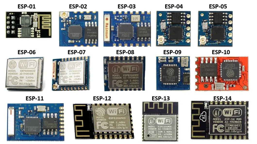
Последняя плата из тех, о которых я расскажу (ESP32 WROOM DevKit v1), построена на контроллере семейства ESP32 — более продвинутой по своим возможностям версии ESP8266.
Все представленные модели можно программировать и загружать прошивки через Arduino IDE точно так же, как при работе с Arduino.
Настройка среды программирования Arduino IDE
По умолчанию среда IDE настроена только на AVR-платы. Для платформ, представленных ниже, необходимо добавить в менеджере плат дополнительную поддержку.
1) Открываем среду программирования Arduino IDE.
http://arduino.esp8266.com/stable/package_esp8266com_index.json, https://dl.espressif.com/dl/package_esp32_index.json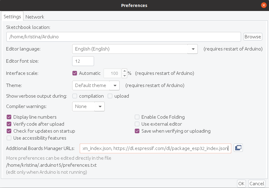
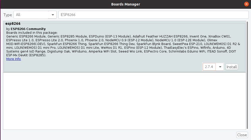
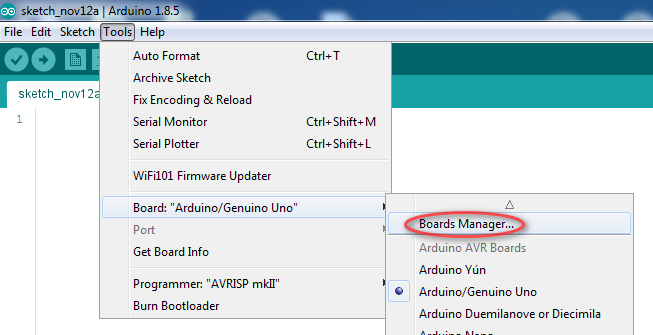
4) В пункте меню Tools (Инструменты) -> Board (Плата) выбираем Boards manager (Менеджер плат).
Находим в списке платформы на ESP8266 и нажимаем на кнопку Install (Установить).
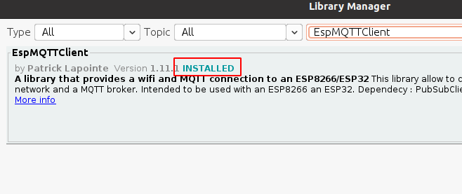
6) Надпись INSTALLED сообщает, что дополнения успешно установлены.

7) Аналогичным образом устанавливаем дополнение для ESP32.
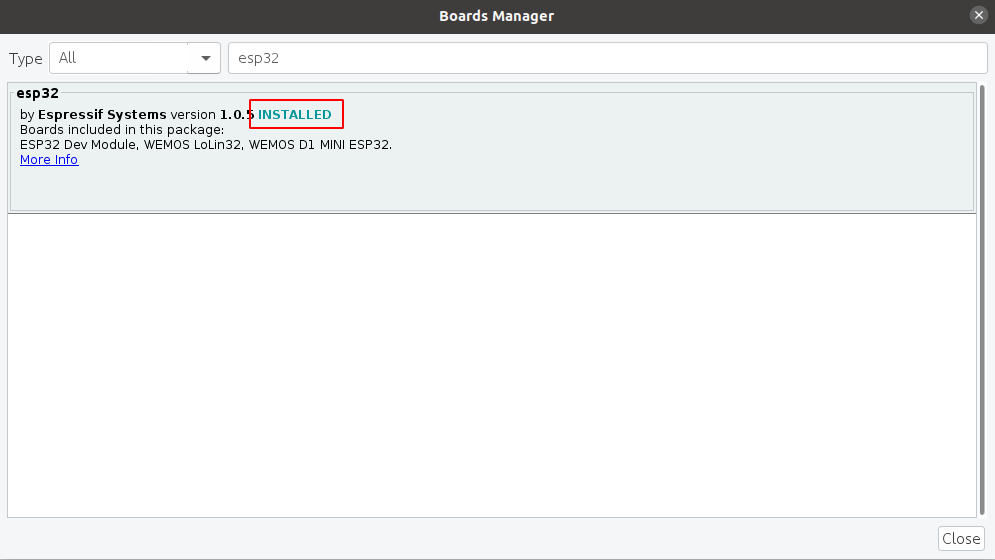
8) Теперь нам доступны к программированию платформы с модулем ESP8266 и ESP32.
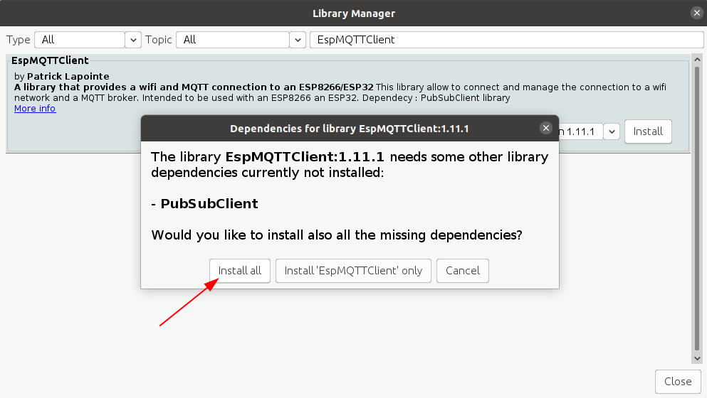
9) Для подключения плат к платформе Интернета вещей используем библиотеку EspMQTTClient. Чтобы ее установить, в пункте меню Tools (Инструменты) выбираем Manage Libraries (Управлять библиотеками). Находим и устанавливаем библиотеку EspMQTTClient. Может появиться сообщение об установке дополнительных библиотек. Выбираем “Install all”.
Примечание — Также для работы с платами понадобится установить драйверы CH340 (WeMos и Goouuu) и CP2102 (для остальных). Их отсутствие повлияет на то, найдет ли Arduino IDE COM-порт, к которому подключена плата.
Код прошивки
Для прошивки всех используемых ниже модулей используем один и тот же код.
- Установка Wi-Fi соединения
- Подключение к объекту на платформе Rightech IoT Cloud по протоколу MQTT
- Отправка рандомных значений по температуре («base/state/temperature») и влажности («base/state/humidity») каждые 5 секунд (PUB_DELAY)
- Получение сообщений о переключении света («base/relay/led1»)
#include "Arduino.h" #include "EspMQTTClient.h" /* https://github.com/plapointe6/EspMQTTClient */ /* https://github.com/knolleary/pubsubclient */ #define PUB_DELAY (5 * 1000) /* 5 seconds */ EspMQTTClient client( "", "", "dev.rightech.io", "" ); void setup() < Serial.begin(9600); >void onConnectionEstablished() < client.subscribe("base/relay/led1", [] (const String &payload) < Serial.println(payload); >); > long last = 0; void publishTemperature() < long now = millis(); if (client.isConnected() && (now - last >PUB_DELAY)) < client.publish("base/state/temperature", String(random(20, 30))); client.publish("base/state/humidity", String(random(40, 90))); last = now; >> void loop() Работоспособность кода будем проверять на платформе Rightech IoT Cloud, именно поэтому в качестве адреса MQTT-брокера указан dev.rightech.io. Идентификаторами клиентов служат идентификаторы объектов, созданных на платформе. Под каждую проверку я завела на платформе отдельный объект, именно поэтому во всех скринах кодов, которые будут далее представлены, отличается только строка .
Прим. — Можно подключаться и к одному и тому же объекту, тогда можно использовать один и тот же код для прошивки всех плат без изменений, однако следите, чтобы в таком случае платы не подключались к одному и тому же объекту одновременно, иначе случится коллизия.
Модули на базе ESP8266
Для работы с модулями на базе ESP8266 есть два варианта:
- Работа с AT командами (в стандартной прошивке Wi-Fi модуль общается с управляющей платой через «AT-команды» по протоколу UART);
- Wi-Fi модуль как самостоятельный контроллер (все представленные модули очень умные: внутри чипа прячется целый микроконтроллер, который можно программировать на языке C++ через Arduino IDE).
В статье будем рассматривать второй вариант — прошивка модулей в виде самостоятельного полноценного устройства. Здесь также есть два варианта прошивки с точки зрения железа:
Рассмотрим второй вариант — использовать адаптер на базе чипа CP2102 (например, такой https://www.chipdip.ru/product/cp2102-usb-uart-board-type-a?frommarket=https%3A%2F%2Fmarket.yandex.ru%2Fsearch%3Frs%3DeJwzSvKS4xKzLI&ymclid=16146772489486451735000001). Обязательно обратите внимание на то, чтобы адаптер позволял выдавать выходное напряжение 3.3 В, не больше!
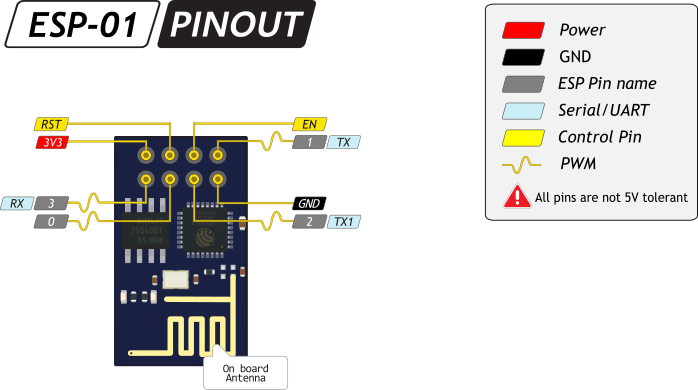
1. ESP-01
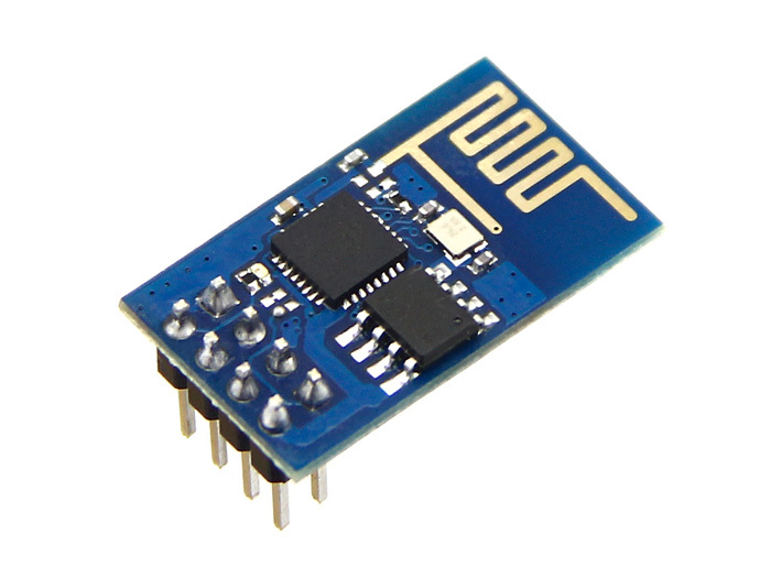
ESP-01 — самый популярный модуль на ESP8266. PCB антенна обеспечивает дальность до 400 м на открытом пространстве.
Внешний вид
Питание
Родное напряжение модуля — 3,3 В. Его пины не толерантны к 5 В. Если вы подадите напряжение выше, чем 3,3 В на пин питания, коммуникации или ввода-вывода, модуль выйдет из строя.
Подключение периферии
2 порта ввода-вывода общего назначения
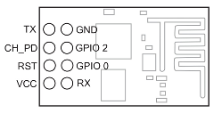
Распиновка
Подключение к IoT
Аппаратная часть
How to Program ESP8266 with Arduino UNO

Here, learn how to Program ESP8266 with Arduino Board. You just need to install the ESP8266 board and make the circuit as per the below-given instructions. Learn the basics and features of ESP8266. We are using the Blink LED program as a sample program.
Step 1: Required Components
Step 2: Installing Board to Arduino IDE
First, install ESP8266 to Arduino IDE. If you have already installed the board to boards manager of Arduino IDE, skip this step else follow the steps
- Start the Arduino IDE
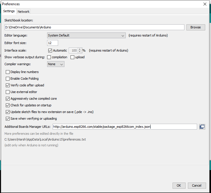
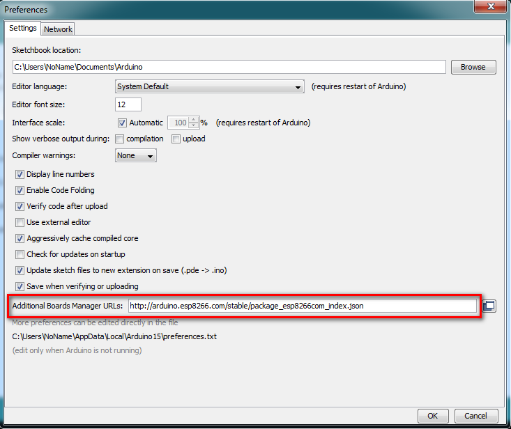
- Go to File > Preferences
- Add the below-given link to Additional Boards Manager URLs
- http://arduino.esp8266.com/stable/package_esp8266com_index.json
Step 3: Circuit Time
Make a circuit as per the given diagram. Connect the CH_PD and VCC line to Voltage Regulator Output, GND and GPIO_0 to Ground. Also, connect the RX and TX lines of both. GPIO_0 is Grounded to enable the programming mode of ESP8266.
Step 4: Program ESP8266 using Arduino
Make the circuit as per the above-given diagram. Power up the Arduino UNO board and wait till the Arduino Board boots up successful. (It will take around 5 seconds) Connect the Arduino Reset pin to Ground. The reset pin is grounded to bypass the Arduino. It will disable the Arduino Board and upload code directly to the ESP8266. Sample program for Blink LED is as below
After the Arduino IDE shows done uploading of Blink LED program, you can connect the LED to GPIO_2 Pin of ESP8266. Please do not connect the LED before or at the time of uploading the program, it can cause some issues in uploading the program.
Note: Disconnect the power supply for one minute if it will show error in uploading the program to ESP8266.
Love it? Share this among your friends:
ESP8266 WiFi module programming with Arduino UNO board
This post shows a quick guide to program ESP8266 WiFi module with Arduino UNO board and how to use Arduino IDE software in order to write codes for this module.
The ESP8266 board contain the microcontroller ESP8266EX (32-bit microcontroller) from Espressif Systems, this low cost Wi-Fi module is a very good choice for hobbyists to build IoT projects. IoT: Internet of Things.
The ESP8266 module comes with AT firmware which allows us to control it with AT commands through serial interface (RX and TX pins).
The most popular ESP8266 module is the ESP-01, it has only 8 pins as shown in the picture below (with pinout):
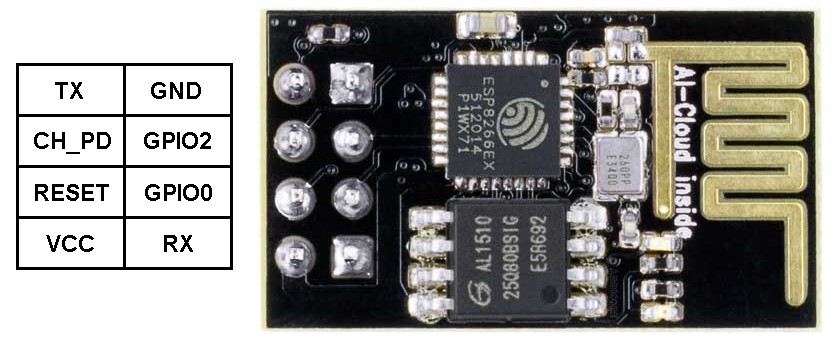
As show above, the ESP-01 board has 8 pins which are:
TX: UART data transmit pin which is also GPIO1 pin
GND: ground pin (0 V)
CH_PD: chip power down pin, used to turn off the ESP8266EX chip, when high the chip is enabled and when low the chip is off, also named as CH_PU (chip power up) and CHIP_EN (chip enable)
GPIO2: general purpose input/output pin 2
RESET: external reset pin (active low), when low the chip is in reset mode
GPIO0: general purpose input/output pin 0
VCC: power supply pin. ESP8266EX chip Operating voltage: 2.5V ~ 3.6V
RX: UART data receive pin which is also GPIO3 pin
ESP8266 Programming with Arduino IDE:
It’s easy to start ESP8266 programming, all what we’ve to do is adding it to the Arduino IDE software.
First, open Arduino IDE and go to File —> Preferences
Add the link below to Additional Boards Manager URLs and click on OK:
http://arduino.esp8266.com/stable/package_esp8266com_index.json
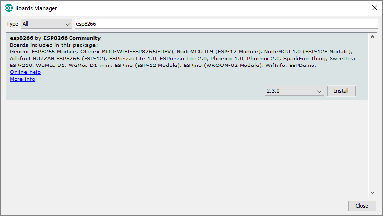
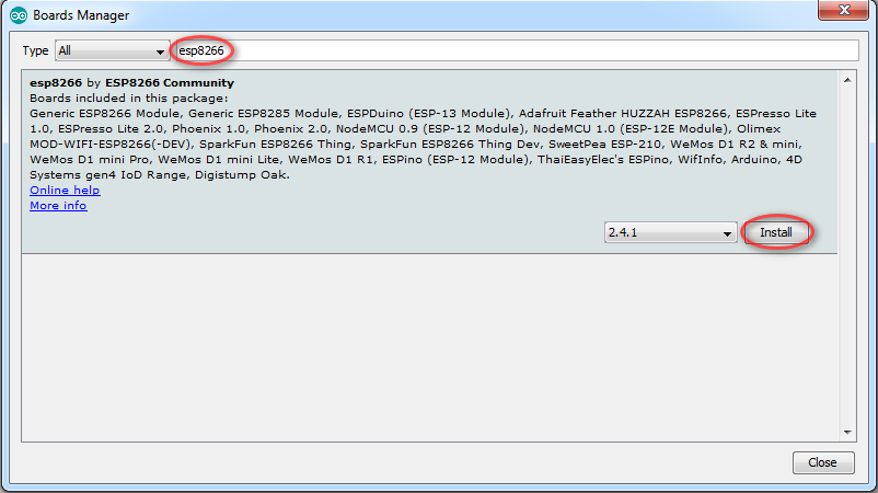
Now go to Tools —> Board —> Boards Manager …
In the search box write esp8266 and click on Install and the installation of the board should start (the installation may take some time depending on the connection speed):
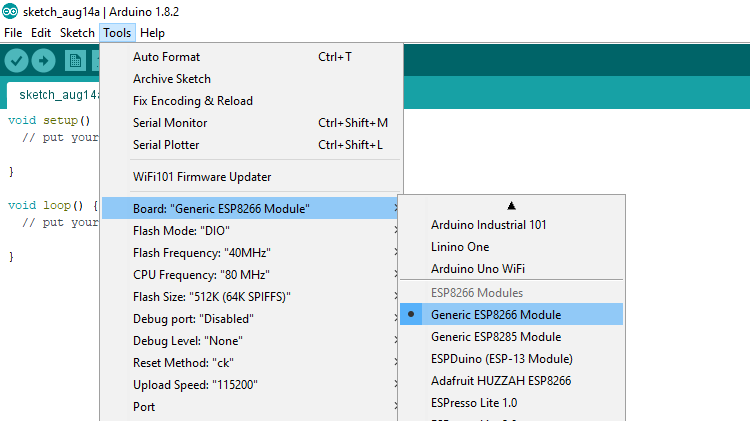
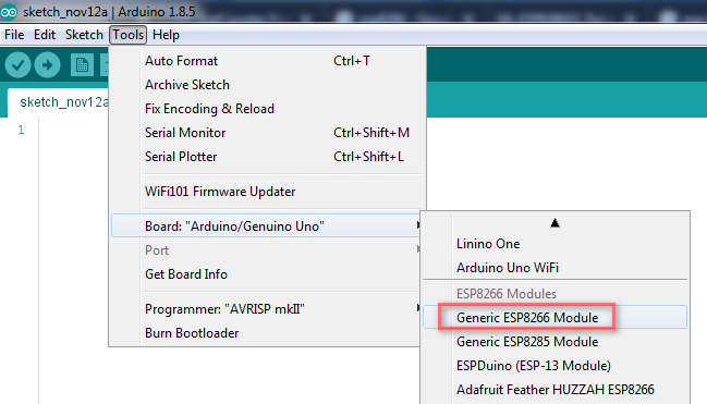
After the installation select the ESP-01 board by going to: Tools —> Board: —> Generic ESP8266 Module
Now every thing is finished and we can start our ESP8266 programming.
Program the ESP8266 (ESP-01) module with Arduino UNO board:
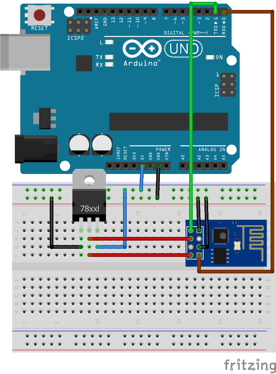
As known the Arduino UNO board contains Microchip ATmega16U2 microcontroller which is used as USB-to-serial converter. This chip (ATmega16U2) can be used to program (flash) the ESP-01 Wi-iF module, circuit connections are shown below:

In the circuit there are 2 resistor one of 1k ohm and the other one of 2.2k ohm. The two resistors are used to step down the 5V which comes to arduino into about 3.43V which goes to the ESP-01 board (connected to RX pin of the ESP-01) because the ESP8266EX chip works with 3.3V only and applying a 5V directly may damage it.
On the other hand, the TX pin of the ESP-01 is connected directly to the Arduino board without any voltage level converter because here the ESP-01 sends data (at 3.3V) to the Arduino board using this pin.
The ESP-01 is supplied with 3.3V which comes from the Arduino board.
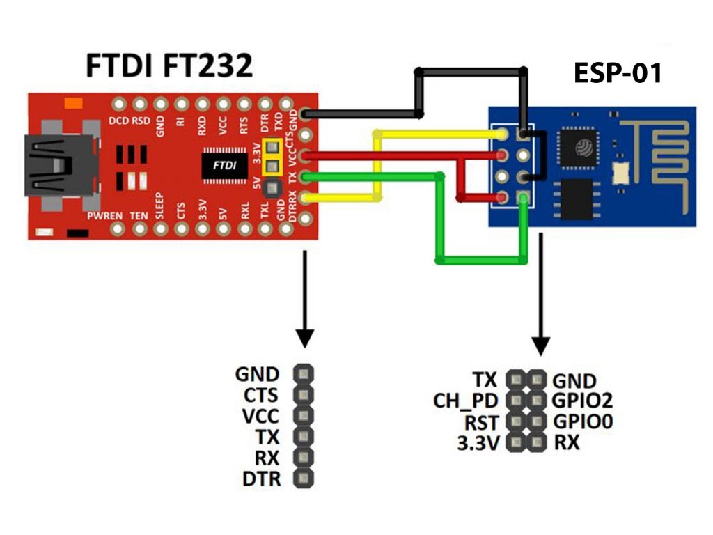
There is other ways to build a programmer for the ESP-01 module for example by using FT232RL USB to serial converter from FTDI Chip which is shown below:
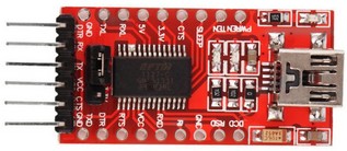
With this module we can choose between 5V and 3.3V (using a jumper) and here we’ve to select 3.3V.
LED Blink with ESP8266 (ESP-01):
This is a simple example which we should start with, it’s the LED blinking example. In this example I’m going to connect one LED to ESP-01 board GPIO2 pin, and make this LED blinks. Circuit diagram is shown below:
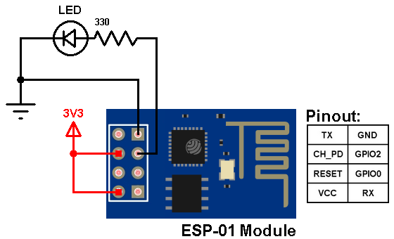
The LED is connected to pin GPIO2 of the ESP-01 module through a 330 ohm resistor.
The ESP-01 module needs a 3.3V supply. We can get the 3.3V for example from Arduino UNO board, or using AMS1117 3V3 voltage regulator which steps down 5V into 3.3V, or directly from 3.3V source.
Arduino code for ESP8266 module: